
So, you have set up your desk and all the components have arrived. Now you are looking at a pile of wires and sensors. What do you do next? This is the exciting part of making your own robot. Today we are going to take all the required parts from your DIY Robotics Lab and make something very special. We are going to use those wires and components to make a Robot that can think.
In this guide, we are building an Obstacle Avoiding Robot using Arduino. This isn’t just a toy car; it’s a machine that uses “eyes” to see walls and “brains” to decide where to go. It is the perfect first project to spark a lifelong love for STEM.
Table of Contents
1. What Exactly is an Obstacle-Avoiding Robot?
Before we pick up a screwdriver, let’s understand the “logic.” Imagine walking through a dark room with a flashlight. You shine the light; if you see a wall, you stop and turn. If the path is clear, you keep walking.
An Obstacle Avoiding Robot using Arduino does exactly the same thing.
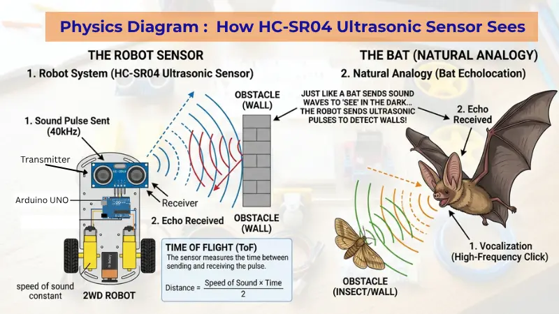
- The Sensors (Eyes): It uses an Ultrasonic sensor to send out sound waves (like a bat) from it’s transmitter. These waves travel through the air, bounce off nearby objects such as walls, and return to the sensor’s receiver, allowing it to detect obstacles.
- The Arduino (Brain): It calculates how long it took for the sound waves to go to the object and come back. If the object is too close, it sends a command.
- The Motors (Legs): The motors receive that command and turn the wheels away from the danger.
This simple logic of sensing and reacting is what powers every Obstacle Avoiding Robot using Arduino that you see in science fairs and labs. It is the foundation of self-driving cars like Tesla or the delivery drones we see being tested in India today!

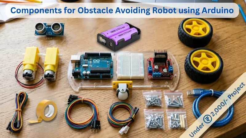
2. Parts You’ll Need (From Your ₹2,000 Lab)
If you followed our previous guide on how to build a robotics lab at home, you already have everything you need. Once you have these components gathered, your Obstacle Avoiding Robot using Arduino is ready for assembly:
- Arduino Uno & USB Cable
- Ultrasonic Sensor (HC-SR04)
- Motor Driver L298N (Available in kit), or L293D Shield, or L293D IC
- 2WD Robot Chassis (with Motors and Wheels)
- 18650 Li-ion Batteries and Holder
- Jumper Wires (Male-to-Female and Male-to-Male)
- Double-sided tape or a small piece of cardboard
3. Step 1: Assembling the “Skeleton”
First, we need to get the mechanical parts ready to built the Obstacle Avoiding Robot using Arduino.
- Fix the Motors: Screw the two BO motors onto your acrylic chassis. Make sure the wires are pointing toward the centre of the board. Connect one wheel to each motor.
- Add the Caster Wheel: This is the tiny “third wheel” at the front that allows the robot to spin easily.
- Mount the “Brain”: Use double-sided tape or the provided screws to fix your Arduino and the Motor Driver onto the chassis.
- Mount the “Eye” of your Robot : Most chassis kits don’t come with a mount for the Ultrasonic sensor.
The “Cardboard Eye” Hack:
Remember when we talked about how to build a robotics lab at home and mentioned using the recycling bin? This is where it comes in!
- Cut a small ‘L’ shape out of a biscuit box.
- Poke two holes for the “eyes” of the sensor.
- Tape the sensor to the cardboard, and then tape the cardboard to the front of the robot.
- Why? It keeps the sensor stable and makes the robot look like it has a “face,” which kids love!
Pro-Parent Tip: Don’t worry about making it look perfect! Engineering is about function first. As long as the wheels are straight and the boards aren’t falling off, you’re doing great.
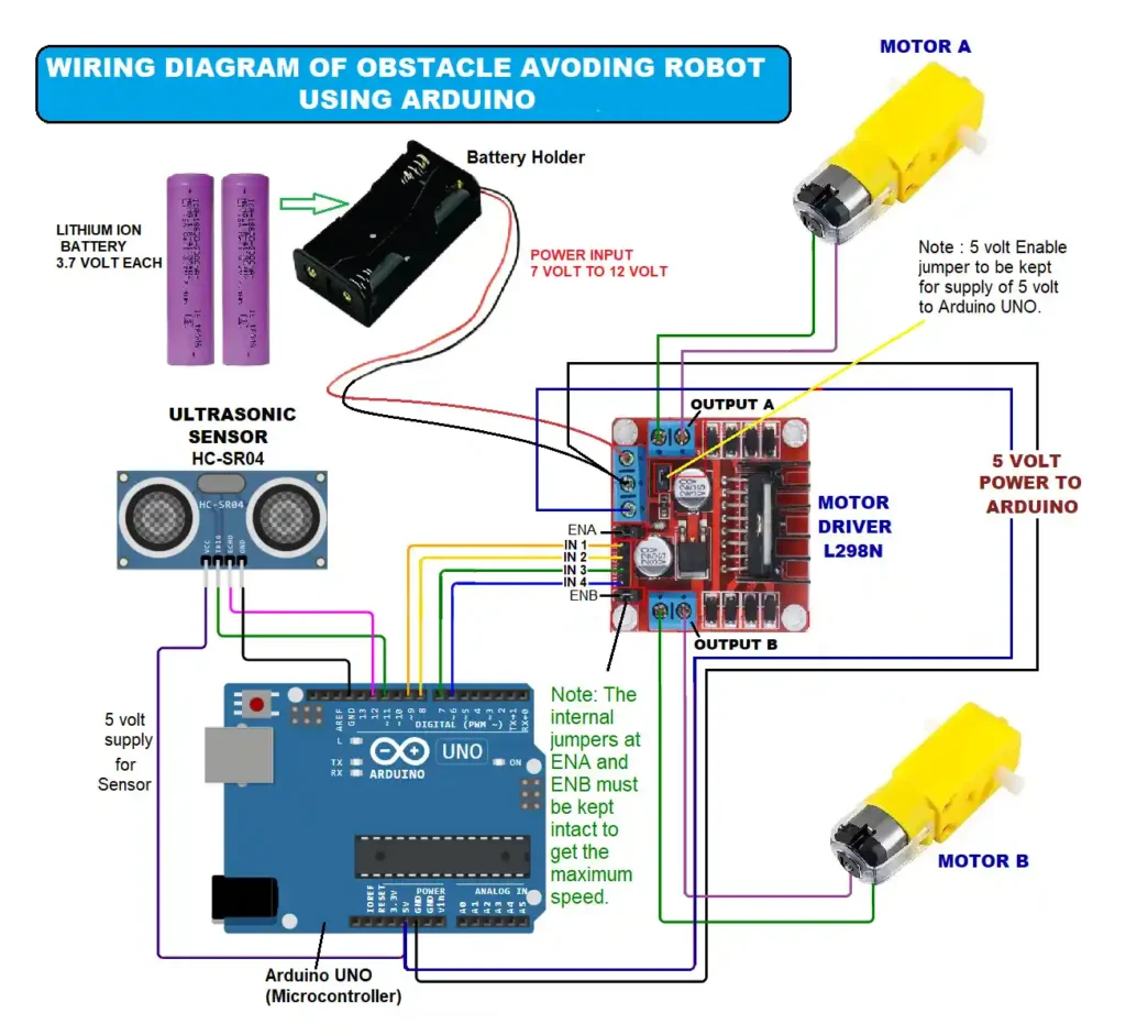
4. Step 2: The Wiring Map (The Nervous System)
Wiring an Obstacle Avoiding Robot using Arduino can look like a “plate of noodles” at first, but if you follow it one wire at a time, it’s simple.
A. Connecting the “Eyes” (Ultrasonic Sensor –HC-SR04)
| Sensor Pin | Connected to Arduino Pin |
| VCC | 5V |
| GND | GND |
| Trig | Pin 11 |
| Echo | Pin 12 |
B. Choosing Your “Traffic Controller” – Motor Driver – L298N (Most Popular and available with you)
This is the red board with the large heat sink. It’s powerful and great for learning.
| Driver Pin | Connected To | Purpose |
| IN1 | Arduino Pin 9 | Motor A Forward |
| IN2 | Arduino Pin 8 | Motor A Backward |
| IN3 | Arduino Pin 7 | Motor B Forward |
| IN4 | Arduino Pin 6 | Motor B Backward |
| ENA / ENB | No external Jumpers | Keep the black internal “jumpers” on, to stay at full speed of motors. |
| 12 Volt | Battery Positive terminal | To power the entire set up |
| GND | Battery Negative & Arduino Uno GND | Common ground for each component |
| 5 Volt | Arduino Uno 5 Volt | To power the Arduino UNO during operation of Robot |
| OUT1 | Motor A – Terminal 1 | Supply to Motor A (+ or -) |
| OUT2 | Motor A – Terminal 2 | Supply to Motor A (- or +) |
| OUT3 | Motor B – Terminal 1 | Supply to Motor B (+ or -) |
| OUT4 | Motor B – Terminal 2 | Supply to Motor B (- or +) |
5. Step 3: Getting Started: Setting Up Your Arduino “Brain”
Before our robot can start “thinking,” we need to install the software that allows us to send instructions to the Arduino UNO.
Phase 1: Installing the Arduino IDE on your PC or Laptop
The Arduino IDE (Integrated Development Environment) is the digital notepad where we write our code.
- Download: Visit the official Arduino Software page.
- Select Version: Download the “Windows Win 10 and newer, 64 bits” installer.
- Install: Run the
.exefile. During installation, if it asks to install “Device Software” or “Drivers,” always click Install. These drivers are the “translators” that help your PC recognize the Arduino.
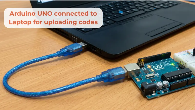
Phase 2: Connecting the Arduino UNO to Your PC
🛑 STOP! Before you plug in the USB: “Make sure your battery is NOT connected to the motor driver yet. We want to ‘flash’ the brain (Arduino) using the USB cable first. This prevents the motors from accidentally spinning and making your robot jump off the desk while it’s still tethered to your computer!”
Now, let’s make the physical connection.
- The Cable: Use the USB A-to-B cable (the blue cable that came with your kit).
- Plug in: Connect the square end to the Arduino and the flat end to your PC’s USB port.
- The Power Light: You should see a small green light labeled “ON” light up on the Arduino board. This means it is receiving power from your computer.
Phase 3: Configuring the IDE
Before we click upload, we must tell the software exactly which board we are using.
- Open the IDE: Launch the Arduino software you just installed.
- Select the Board: Go to Tools > Board > Arduino AVR Boards and select Arduino Uno.
- Select the Port: Go to Tools > Port. You will see a list (like COM3, COM4, etc.). Select the one that says (Arduino Uno) next to it.
- Note: If the port is grayed out, try unplugging the USB and plugging it back in.
6. Step 4: Programming the Logic (Uploading Your First Code)
Now for the exciting part—sending the logic to our Obstacle Avoiding Robot using Arduino :
- Copy the Code: Paste the Master Code we provided below into the IDE window.
- Verify: Click the Checkmark icon (top left). This “compiles” the code to make sure there are no typing errors.
- Upload: Click the Right Arrow icon (next to the checkmark). You will see small orange lights (labeled TX/RX) flashing on your Arduino.
- Success: Once the bottom bar says “Done uploading,” your robot is officially programmed!
Here is the “Humanoid” version of the code:
// --- Pin Definitions ---
const int trigPin = 11;
const int echoPin = 12;
const int ENA = 10;
const int IN1 = 9;
const int IN2 = 8;
const int IN3 = 7;
const int IN4 = 6;
const int ENB = 5;

// --- Parameters ---
int distanceThreshold = 25;
// 255 is absolute maximum speed.
// If the robot moves too fast for the sensor to react, you can lower this to 200.
int motorSpeed = 255;

void setup() {
  Serial.begin(9600);

  pinMode(ENA, OUTPUT);
  pinMode(IN1, OUTPUT);
  pinMode(IN2, OUTPUT);
  pinMode(IN3, OUTPUT);
  pinMode(IN4, OUTPUT);
  pinMode(ENB, OUTPUT);
  pinMode(trigPin, OUTPUT);
  pinMode(echoPin, INPUT);

  Serial.println("Robot Initializing at MAX SPEED...");
  delay(2000);
}

void loop() {
  int distance = getDistance();

  Serial.print("Distance: ");
  Serial.print(distance);
  Serial.println(" cm");

  if (distance <= distanceThreshold && distance > 0) {
    avoidObstacle();
  } else {
    moveForward();
  }

  delay(50);
}

int getDistance() {
  digitalWrite(trigPin, LOW);
  delayMicroseconds(2);
  digitalWrite(trigPin, HIGH);
  delayMicroseconds(10);
  digitalWrite(trigPin, LOW);
  long duration = pulseIn(echoPin, HIGH);
  int cm = duration * 0.034 / 2;
  // Filter out zero readings which sometimes happen with sensors
  if (cm == 0) return 100;
  return cm;
}

// --- Movement Functions ---

void moveForward() {
  Serial.println("Status: Moving Forward (MAX)");
  // Since jumpers are removed, we must tell pins 10 and 5 to be HIGH
  analogWrite(ENA, motorSpeed);
  analogWrite(ENB, motorSpeed);
  digitalWrite(IN1, HIGH);
  digitalWrite(IN2, LOW);
  digitalWrite(IN3, HIGH);
  digitalWrite(IN4, LOW);
}

void moveBackward() {
  Serial.println("Status: Reversing (MAX)");
  analogWrite(ENA, motorSpeed);
  analogWrite(ENB, motorSpeed);
  digitalWrite(IN1, LOW);
  digitalWrite(IN2, HIGH);
  digitalWrite(IN3, LOW);
  digitalWrite(IN4, HIGH);
}

void turnRight() {
  Serial.println("Status: Turning Right (MAX)");
  analogWrite(ENA, motorSpeed);
  analogWrite(ENB, motorSpeed);
  digitalWrite(IN1, HIGH);
  digitalWrite(IN2, LOW);
  digitalWrite(IN3, LOW);
  digitalWrite(IN4, HIGH);
}

void stopMotors() {
  Serial.println("Status: STOPPED");
  analogWrite(ENA, 0);
  analogWrite(ENB, 0);
  digitalWrite(IN1, LOW);
  digitalWrite(IN2, LOW);
  digitalWrite(IN3, LOW);
  digitalWrite(IN4, LOW);
}

void avoidObstacle() {
  Serial.println("!!! OBSTACLE !!!");
  stopMotors();
  delay(200);

  moveBackward();
  delay(600);

  stopMotors();
  delay(200);

  turnRight();
  delay(500); // At max speed, it will turn very fast, so delay is shorter

  stopMotors();
  delay(200);
}
Pro-Tip for Parents: The “Safety Wait”
In our code, we added a delay(2000); at the start. This gives you 2 seconds after the upload is finished to unplug the USB cable and place the robot on the floor before the motors start spinning!
7. Step 5: The “First Breath” Test of Obstacle Avoiding Robot using Arduino
The Moment of Life!
Now that your Arduino has its “instructions” (the code), it’s time to cut the umbilical cord (the USB cable) and let it run on its own power.
1. The Final Safety Scan
Before we connect the battery, do a 10-second “Nerve Check”:
- Are there any loose wires touching each other?
- Is the red battery wire going to VCC (7V to 12V) and the black to GND on the L298N?
- Crucial: Is the robot on a stand (like a small box) so the wheels can spin freely without it zooming off the table?
2. Connecting the Power
Snap your Battery into its clip.
- You will see the red LEDs on both the L298N and the Arduino light up.
- Thanks to our code’s 2-second delay, you have a moment to breathe before anything moves!
3. The “Free-Spin” Test
Hold the robot in the air and place your hand 10cm in front of the sensor.
- The wheels should stop, reverse, and then one wheel should spin faster to “turn.”
- If a wheel is spinning backward when it should be going forward, simply swap the two wires of that specific motor on the L298N green terminals.
4. The Maiden Voyage
Place your robot on a smooth, flat floor (tiles or wood work best).
- Press the Reset Button on the Arduino.
- Watch as it moves toward a wall, “sees” it, and makes its first successful turn!
8. Troubleshooting: Why Isn’t My Robot Moving?
Don’t panic! Even professional engineers face “bugs.” If your obstacle avoiding robot using arduino isn’t working, check these three things:
- The Battery Level: Motors need a lot of “juice.” If your batteries are low, the Arduino might turn on, but the motors won’t have the strength to spin.
- The Wire “Jiggle”: Sometimes a jumper wire looks connected but isn’t. Gently jiggle each wire to make sure it’s snug.
- Motor Direction: If your robot spins in circles instead of going forward, swap the two wires of one motor on the driver board. This reverses the direction!
9. Educational Value: The NEP 2020 Connection
Building an Obstacle Avoiding Robot using Arduino isn’t just a fun weekend project; it’s a masterclass in Experimental Learning. According to India’s NEP 2020, kids should learn through discovery.
When a child sees their robot stop before hitting a wall, they aren’t just seeing code—they are seeing Physics (Sound waves), Mathematics (Distance calculation), and Logic (Decision making) all working together. This is “Integrated STEM” at its best.
Beyond this integrated learning, the foundational ideas of physical construction and the logic of program coding forms a powerful platform. The techniques learned here—such as interfacing sensors, controlling motor drivers, and managing program flow—are directly transferable. Once a child has successfully built and coded this obstacle avoider, they have the confidence and the core competencies to tackle a vast world of other, more complex projects on the Arduino platform, such as a Line Follower Robot, a maze-solving rover, or even a home automation system. This project isn’t just an end goal; it’s the essential gateway to a lifelong journey into the world of robotics and invention.
10. Level Up: Challenges for Your Child
Once the basic robot is working, don’t stop there! Upgrading your obstacle avoiding robot using arduino is the best way to keep the learning journey alive. Encourage your child to try these challenges:
- Add a Buzzer: Make the robot “beep” when it sees a wall.
- Speed Control: Try to make it move faster in open spaces and slower near obstacles.
- Different Surfaces: Does the robot work on carpet? What about a tiled floor? Why is there a difference? (Hint: It’s Friction!)
11. Frequently Asked Questions (FAQ) for Parents
Q: Is it safe for my 9-year-old to build this alone? A: Yes! This project uses low-voltage batteries (under 9V), which are completely safe to touch. However, we recommend adult supervision during the “Battery Connection” phase to ensure wires don’t touch each other and cause a spark.
Q: My robot moves backward when it should go forward. What should I do? A: This is the most common “oops!” moment. Simply swap the two wires of the motor that is going the wrong way where they plug into the motor driver. It will instantly fix the direction.
Q: Can we build this without a laptop? A: Absolutely. If you have an Android tablet or phone, you can use the PictoBlox app and a small “USB OTG” adapter to upload the code to your Obstacle Avoiding Robot using Arduino.
Q: Do we need to buy a new Arduino for every project? A: No! One of the best things about the Arduino is that you can erase the old code and upload a new project as many times as you like. Your robot can be a wall-avoider today and a line-follower tomorrow.
Q: What is the total cost if we already have the lab? A: If you have followed our ₹2,000 lab guide, the cost for this project is ₹0. You are simply using the “brain” and “muscles” you already own.
12. Conclusion: From Students to Creators
The moment your child’s Obstacle Avoiding Robot using Arduino makes its first successful turn, they have officially joined the “Maker” movement. They have proven that they can take raw components and create something intelligent.
This project is the first of many. Now that you have a working mobile base, you can later add Bluetooth for phone control or even a robotic arm for picking up objects. The sky is the limit!
Enjoyed this build? Share a photo of your robot in the comments.
🚀 What’s Next?
“You’ve built the robot, but why does this matter for your child’s development? In our next post, we’re diving into the ‘Screen-Free’ revolution—how robotics like this one are the secret weapon for teaching STEM without the side effects of more screen time. Stay tuned!”

Samir Sen is a retired Indian Railways Signalling Engineer with over 30 years of experience in railway signalling systems and safety operations. He also served as a faculty member at a Zonal Signalling Training Institute of Indian Railways, delivering theoretical and practical training in signal engineering. Through SSEN Techno, he simplifies robotics and STEM education for learners and beginners.